Nos sites web pays
 Arabie Saoudite
  Australie
  Brésil
  Chine
Chine  Corée du Sud
  Danemark
  États-Unis
  France
  Inde
Inde  Indonésie
  Irlande
  Italie
  Malaisie
  Norvège
  Nouvelle-Zélande
  Pologne
  Royaume-Uni
  Singapour
  Suède
Suède  Taïwan
  Thaïlande
  Vietnam
 Nos autres sites web
Nos sites web pays
Nos autres sites web
Nos sites web pays
Nos autres sites web
Nos sites web pays
Nos autres sites web
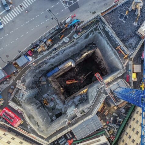
Constructibilité
Constructibilité
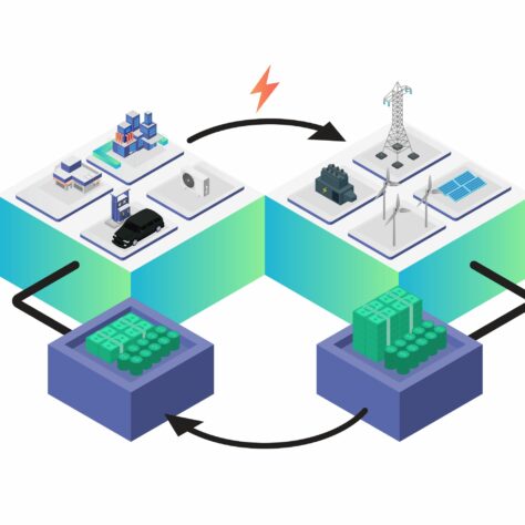
Transition énergétique
Transition énergétique
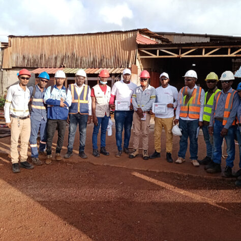
3S - Santé, sécurité et sûreté
3S - Santé, sécurité et sûreté
Planification des transports
Planification des transports